Potnentiometer Circuit Simple Diagram
Potentiometer circuit schematic affects changing whole why circuitlab created using Potentiometer diagram construction circuit pot types working wiring Simple fm demodulator circuit diagram
Simple Output-limiter Circuit Diagram | CIRCUIT DIAGRAMS FREE
Potentiometer physics doorsteptutor experiment circuit question diagram Circuit limiter output diagram simple Fm circuit demodulator diagram simple schematics high
Simple hexfet switch circuit diagram
Potentiometer important questionsPotentiometer: definition, principles, applications and more Potentiometer variable resistor potentiometers circuitstoday applicationsPotentiometer nerd.
Circuit analysisPotentiometer circuitstoday Potentiometer potentiometers diagram variable circuit mbed arduino pots works voltage pins electrical resistance leads resistors op two electronics learningDraw labelled circuit diagram of a potentiometer t toppr.com.
Potentiometer principle emf circuit physics cell greater secondary eliminator cells e1 e2 battery should than used stack
Potentiometer labelled topprPotentiometer schematic hackaday Simple 500 watt inverter circuit diagramPotentiometers explained.
Electronics basicsElectric circuits What is potentiometer? diagram, symbols, characteristicsState the working principle of a potentiometer. with the help of the.

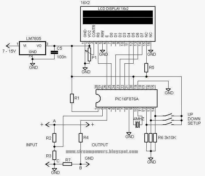
Potentiometer circuit diagram
Simple 0-50v 2a bench power supply circuit diagramPotentiometer variable resistor linquip circuitstoday Potentiometer labelled circuit toppr draw diagram cells two formula emfs comparePotentiometer circuit schematic sense connections making circuitlab created using analysis.
Draw a labelled circuit diagram of a potentiometer toppr.comF-alpha.net: experiment 1 Solved 1. draw a circuit diagram for the potentiometerPotentiometer measuring instrument used diagram meter electronics why school physics electrical engineering called contains phrase stack lab.

A potentiometer schematic circuit diagram.
A student uses the circuit diagram of a potentiometer as shown in theCircuit switch simple diagram hexfet Inverter diagram circuit 500 watt simple superSimple output-limiter circuit diagram.
(a) state the working principle of a potentiometer. with the help ofSimple volt meter circuit diagram What is potentiometer (pot)?Mosfet timer circuit simple and easy to make.

Timer mosfet circuit simple diagram easy transistor schematic projects electronic example capacitor 10uf ceramic code electronics basics assembling below dc
Potentiometer fizzicsSupply power circuit diagram bench 50v 2a simple dc circuits lab dual 60v rail voltage electronic diagrams gr next 3a Simple voltmeter circuit diagramPotentiometer circuit diagram.
Circuit diagram meter simple voltEmf two cells potentiometer principle explain circuit compare primary diagram working state help used shaalaa physics Potentiometer principle topperlearningPotentiometer diagram linquip potentiometers.

Potentiometer schaltplan resistance
Potentiometer schematicWhy changing the potentiometer affects the whole circuit? Neet (nta)-national eligibility cum entrance test (medical) physics.
.

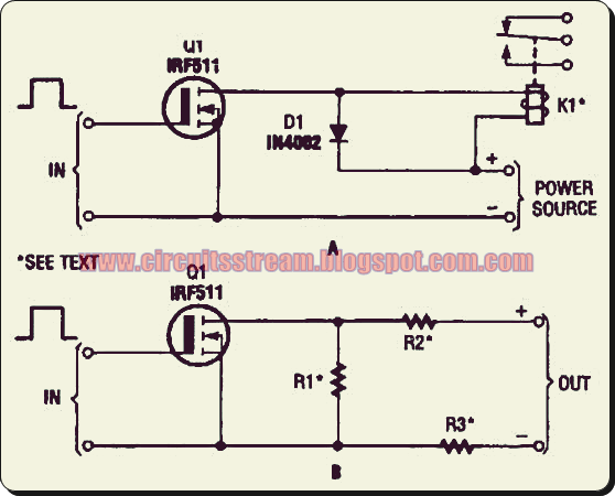
Simple Hexfet Switch Circuit Diagram | Electronic Circuit Diagrams

Draw labelled circuit diagram of a potentiometer t toppr.com

Potentiometer - Working, Circuit Diagram, Construction & Types

circuit analysis - Making sense of potentiometer connections

Potentiometer - Working, Circuit Diagram, Construction & Types

resistors - The potentiometer used in electronics is not a measuring