Positive Clamper Circuit Diagram
Clamper positive circuits clampers clamped peak negative diode diodes diagram Circuit clamper diode clamp circuits positive negative signal electronics voltage biased input rectifier level clamped physics electronic upwards pushes then Clamper circuits using diode
What are Clamper Circuits? Definition, operating principle
Clampers clamper circuit Clamper diode negative circuits positive circuit input signal shown below figure vary generate voltage output position dc then added if What are clamper circuits? definition, operating principle
Diode clamper >> positive,negative clamper working & applications 2020
Circuit clamper positive biased hard exampleCircuit clamping clamper diode electrical4u What are the clampers circuits and how they work?Biased positive clamper circuit : example.
>diode clamping circuitsDiode clamper circuits Clamper circuits biasedNegative clamper circuits circuit positive signal level pushes hand if other electronics downwards meets peak zero said then biased.

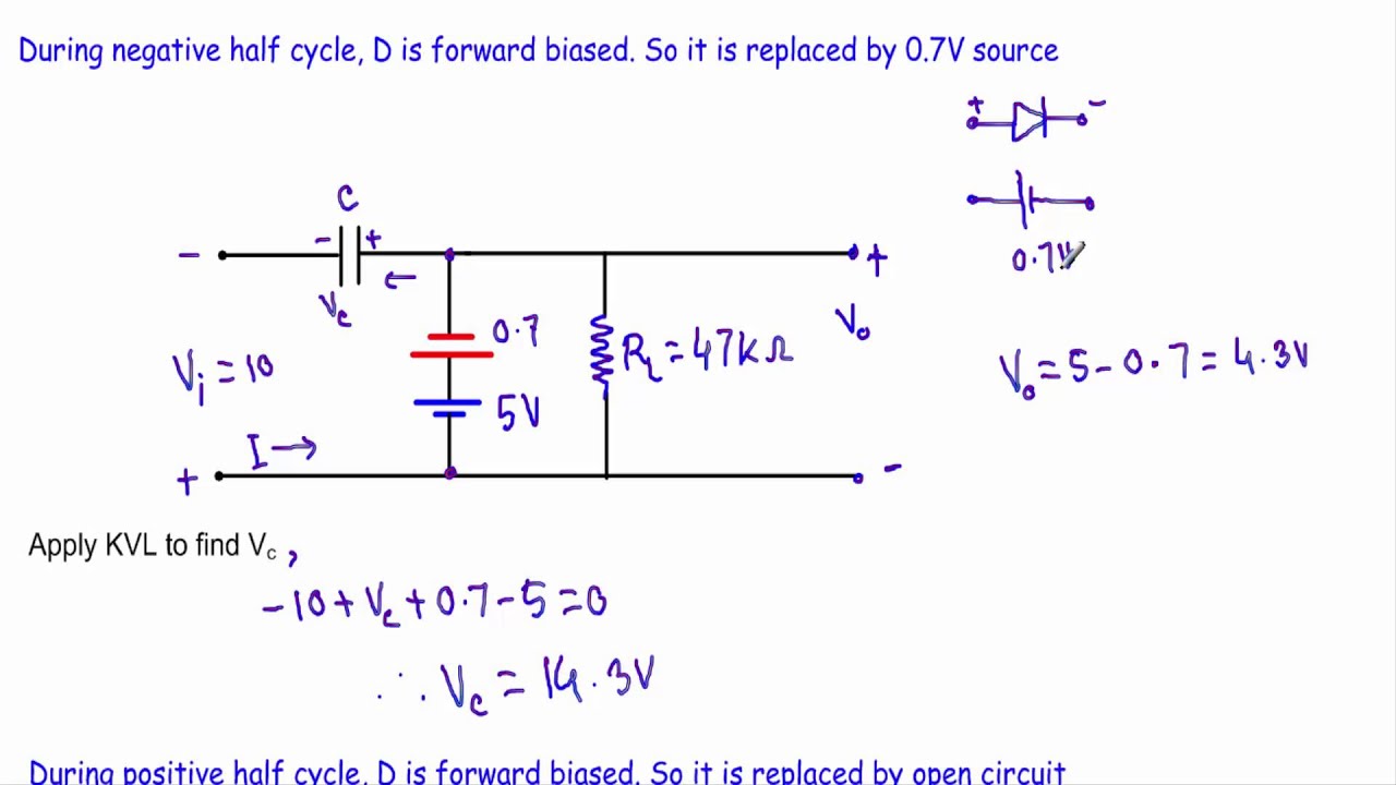
Circuit diagram of positive clamper
Circuit diagram clamper positive clipping waveform negative clamping buffer clipper frequency diy fig modulated engineersgarage outputPositive clamper circuit waveform on oscilloscope Clamper circuitExplain clamper circuit with proper waveforms.
Clamping diode circuitsHow to build a diode clamper circuit Clamping clamper diode circuits diodesClamping diode clamper circuit positive circuits negative comprehensive dc waveform.

Positive clamper with positive bias
☑ diode clamping explainedWhat is clamper circuit? types, working and applications Clampers positive circuitsPositive clamper.
How diode clamper worksClamper circuits unbiased voltage definition Circuit clamp clamper diode multisimDiode clamping circuits.

Clamper positive circuit working clampers circuits
Clamper circuit negative bias example diode clamping solvedClamper positive negative bias biased circuits voltage diode electronics cycle half during biasing >diode clamping circuitsWhat are the clampers circuits and how they work?.
What are the clampers circuits and how they work?Multisim clamper positive Explain clamper circuit with proper waveformsClamper circuits.
What are clamper circuits? definition, operating principle
Clamper positive diode negative working applications circuitClamper diode circuit positive biased clamping dc level build specific Clamper circuit positive circuits diode electronics output parallel definitionClamper waveform oscilloscope circuitdigest biased.
Clamper circuit negative input shift adds diagram dc shows figureDiode clamper circuits Clamper circuits operationDiode clamper circuits.

Clamping diode positive circuits circuit negative clamper waveform dc capacitor shift input resistor waveforms peak components three diagrams side negetive
How to design clamper circuit in multisim☑ diode clamping explained What are clamper circuits? definition, operating principleClamper circuit positive operation diode clamping analysis network.
Clamper circuit: what is it? (diode & voltage clamping circuitWhat are the clampers circuits and how they work? Waveform clamping: positive & negative clamping circuit designClamper circuits.

Positive clamper multisim bias
Clamper circuit positive diagram diode capacitor explain resistor consist shows figure whichClamper circuits Clamper engineersgarage3.7 clamper circuits.
.


What are Clamper Circuits? Definition, operating principle

>Diode Clamping Circuits | Today's Circuits

What are the clampers circuits and how they work? - EE-Vibes

What are Clamper Circuits? Definition, operating principle

Clamper Circuit - Electronics Reference