Pll Circuit Diagram
Pll fm demodulator diagram block circuit using theory working Diagram block pll phase loop lock basic ic locked explain following shows figure written ago Frequency multiplier circuit
What are Phase-Locked Loops (PLL)? Definition, Block Diagram, Working
Pll phase loop locked diagram block detector lock vco circuit lpf fm fsk demodulation operation principle operating loops modes digital Circuit pll khz seekic locked monitoring experimental headphones phase loop theory operation gives audio range simple easy Pll oscillator – simple circuit diagram
Phase locked loop operating principle and applications
Pll circuit with 3 ic'sFile:all degital pll (block diagram-2).png Circuit pll fm demodulator circuits diagram phase using ic project audio rf simple diagrams circutsPll exciter.
Pll oscillator block lock vco semiconductorPll_ir_laser_light_receiver Pll composite oscillator circuit composed of cd4046Pll fm detector.

Loop pll circuit synthesizer phase lock frequency circuits soldering spirit figure gr next
Application of pll and pic to alert signaler for the deafPll fm transmitter circuit power low synthesized schematic circuits broadcast rf gr next posted reference counter Pll block diagram degital arduino file digital basic commons wikimedia implement descriptionPll fm demodulator – simple circuit diagram.
Block diagram of the pll circuit operating at turn-on.Circuit laser pll receiver ir light diagram circuits seekic transmitter communication pfm ic gr next Fractional pll block diagramPll fm demodulator circuit diagram circuits phase loop locked schematic chip vco kenwood adding detector voltage rf am gr next.

Pll instruments
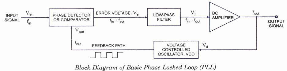
Illustrates a block diagram showing the structure of the pll. this pllSimple pll circuit Pll diagram block principle phase loop locked applications workingPll exciter vco seekic.
A basic pll circuit.Pll circuit configuration. Phase locked loop (pll) operating principle phase detector vco lpfPll circuit exciter circuits diy schematics schematic vco diagram rf signal control digital electronics transmitter ic switches thumbwheel.

Frequency multiplier circuit using pll divider diagram programmable thumbwheel switches projects parts list
What are phase-locked loops (pll)? definition, block diagram, workingPll fm transmitter circuit 88 diagram 108mhz 500mw diy using schematics electronic schematic electronics rf zone circuits ic vco amplifier Pll block diagram circuit figurePll exciter.
Pll phase locked analog frequency fundamentals diagram loops configurationPll circuit detector Injection lock oscillator • pll with the nb3n502Schematic diagram of the pll simulation circuit.

Pll oscillator wave circuit medium frequency 2009 diagram phase circuits loop locked gr next schematic sine simple low tag adam
Spirit soldering: pll frequency synthesizer step 1 khzBlock pll loops Pll fractional diagram block diorio talks cs washingtonZmcpy fm broadcast ::::: pll mc145151.
Pll circuit with 3 ic'sPll publication illustrates oscillator Pll transmitter fm circuit schematic circuits diagram radio am phase loop locked low power antenna 4w broadcast rfCd4046 pll circuit oscillator composite diagram composed seekic phase loop ic.

1_9_khz_pll
Analog_pll_as_fm_demodulatorPll simulation Analog circuit fm pll demodulator diagram seekic phasePll fm transmitter circuit under repository-circuits -42597- : next.gr.
A basic pll circuit.Pll fm circuit detector diagram frequency demodulator current 565 ic reduce electric part Phase-locked loop (pll) fundamentals500mw pll fm transmitter 88-108mhz.

Pll fm demodulator circuit using xr2212 . design, working priciple, theory
Pll ghz vco mhzDescribe the basic block diagram of the phase locked loop (pll). Pll fm demodulator circuitelectronics project circuts.
.

PLL Composite Oscillator Circuit Composed of CD4046 - Automotive

illustrates a block diagram showing the structure of the PLL. This PLL

Injection Lock Oscillator • PLL with the NB3N502

PLL circuit with 3 IC's - Discussion Forums - National Instruments

ANALOG_PLL_AS_FM_DEMODULATOR - Basic_Circuit - Circuit Diagram - SeekIC.com