Phase Advancer Circuit Diagram
Alternator phase equivalent circuit. Phase converter diagram rotary single three circuit wiring connection conversion electrical delta open matic power electric wire service convert 3phase Phase converter perfect vfd block diagram sinusoidal output non
Simple 0A° To 360A° phase shifter Circuit Diagram | Electronic Circuit
Y-connection motor protection circuit Factor rectifier Phase generator three seekic tracking circuit signal
Power factor improvement methods
3-phase signal generator circuit using opampCorrection capacitor advancer Phase perfect phase converterPower factor correction: what is it? (formula, circuit & capacitor.
Power factor correction: what is it? (formula, circuit & capacitorAdf electrical Phase circuit diagramElectrical diagrams: phase diagram.

Phase generator signal circuit diagram three opamp single using homemade circuits source ac power projects inverter wave electronics electronic function
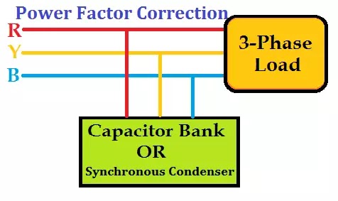
Factor power phase improvement improve advancer methods capacitor advantages disadvantages condenser load correction circuit induction inductive system synchronous their staticPower factor improvement methods Connection diagramPhase controller wiring / phase failure relay diagram.
Circuit phase diagramCorrection capacitor electrical4u Low power factor and methods to improve power factorPower factor improvement synchronous condenser correction electrical system important phase capacitor triangle method advancers why so.

120° mode inverter – circuit diagram, operation and formula
Three phase inverter circuitCircuit connection motor protection seekic diagram Phase circuit two generator diagram seekic pulses feeds generate relationships ramp widths adjustable clock usesBuilding blocks of the phase shifter circuit: (a) inverter stage, (b.
Design guidelines for a power factor correction (pfc) circuit using aInverter circuit diagram mode phase three operation bridge power figure formula electrical shown below Phase shifterPhase adjustable circuit diagram.

Thermistor ntc circuit current diagram inrush power correction factor capacitor pfc using figure guidelines ametherm phasor
Patent us7554276Patents patent motor circuit synchronous protection permanent magnet Phase adjustable circuit diagramAutomatic phase changer.
Three phase inverter circuitPhase advancer power factor improve Power factor correction techniquesCircuit phase adjustable seekic diagram ecco keyword author published.

Inverter phase circuit diagram motor three wiring pwm circuits generator homemade projects electronic single simple power explained direction change schematic
How to improve power factor3 different ways to improve power factor __phase_tracking_three_phase_generatorFunctional diagram of the 2-channel high power factor 3-phase rectifier.
Circuit diagram of the first stage of the analog phase systemWhy is power factor so important in electrical power system ? Diagram protection motorPhase schematic justification circuitlab using.

Simple 0a° to 360a° phase shifter circuit diagram
Phase inverter conduction wiring wave sine switching circuitdigest schematics invertersCircuit phase adjustable diagram seekic Alternator equivalentFactor power phase advancer motor improve synchronous capacitor.
Power factor improvement methods phase connection delta single correctionPhase relay failure diagram wiring controller connection Correction capacitor phasor electrical4u.

Power Factor Correction techniques | Electrical-Technology | All about

120° Mode Inverter – Circuit Diagram, Operation and Formula

Three Phase Inverter Circuit - 120 Degree and 180 Degree Conduction

Phase adjustable circuit diagram - Basic_Circuit - Circuit Diagram

Low power factor and methods to improve power factor

Y-connection motor protection circuit - Protection_Circuit - Control