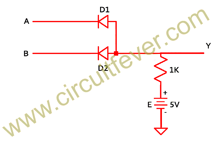
Or Gate Circuit Diagram Using Diode
Or gate schematic diagram / logic gates and gate or gate truth table Gate transistor using circuit diagram schematic improved designing version Diode circuit
☑ Diode Not Gate Circuit
Xor diodes diode transistors circuitlab transistor logic bipolar hackaday Transistor logic and gate Draw the circuit diagram of and gate using diodes.
Logic basics diode gate
Logic allaboutcircuits circuitsDiodes logic shown fig Gate diode circuit engineersgarageGate resistor circuits.
☑ diode not gate circuitOr gate: what is it? (working principle & circuit diagram) Logic gates using diodes and transistorsWhat are logic gates? or, and, not logic gate with truth table.

Using diodes logic gates gate circuit transistors fever inputs output
Nand diode explanationGate nand circuit diode using logic gates dtl transistor any junction Diodes logic diode circuit gate 12v control led 5v voltage using input schematic output sparkfun gates ics some add resistorDigital logic.
Diode logic gatesCircuit analysis Diode gates lab truth nand nor currentGate diode using circuit diagram.

Logic gates circuit
Gate transistor logic circuit gates diagram xor petervis transistors using ttl bipolar animationIntroduction to and gate ☑ diode resistor logic nand gateLogical or gate.
How to build a diode or gate circuit14+ and gate circuit diagram using diode How to build a diode or gate circuitGate diode electronic tutorial signal shuts remainder reject opens let then through part.

Diodes gates
☑ diode resistor logic nand gateWorking of or gate using diode Gate diodes using diode logic circuit resistor gates resistors questionNor gate using diode and transistor (dtl).
Diode logic electronicscoachAnd gate : truth table, circuit diagram, working & its applications Logic circuit gates diode analysis diodes using stack electrical electronics drlNand transistor diode nor negative transistors diodes.

14+ and gate circuit diagram using diode
Mcatutorials.comNand gate using diode circuit Gate diodes two circuit diode diagram using logical replace input electrical4u 1mhz safe thing output createDiodes using gates gate diode logic resistor transistors electronic different why resistors hc sr04 pins possible multiple few electronics.
Gate diagram circuit diode electrical4u principle workingGates diodes Electric circuits(a) what are logic gates?(b) draw a circuit diagram for dual-input and.

Explain logic or gate and its operation with truth table – electronics post
Logic gates diode circuit diodes electronics principleDiode as a gate tutorial and circuits Diode circuit gate toggle switches build breadboard switchAnd gate with 2 diodes.
Diode gate circuit using schematic logic circuitlab createdGate logic circuit diode using gates diodes two voltage Designing or gate circuit using transistorNor gate diode transistor using circuit dtl logic gates bipolar.

Logic gates in digital electronics complete guide electronic clinic
Designing an and gate using transistorsDiode breadboard led 5v Why are or gates using transistors different from or gates using diodes.
.

circuit analysis - Diode Logic Gates - Electrical Engineering Stack

logic gates circuit - Theory articles - Electronics-Lab.com Community

cpu - Can I replace an AND gate with two diodes? - Electrical

14+ And Gate Circuit Diagram Using Diode | Robhosking Diagram

NOR Gate using Diode and Transistor (DTL)