Notch Filter Circuit Diagram Explanation
Op amp Notch filter (bandstop): what is it? (circuit & design) Hz notch amps
Simple Adjustable Notch Filter Circuit Diagram | Wiring Diagram circuit
Notch filter circuit project Designing notch filter circuits Notch filter circuit active stop band electrical4u transfer function
Notch circuits precision incorporates
Notch filter audio bandpass circuit diagram gr next60 hz notch filter circuit Notch filterTwo op-amps 60 hz notch filter – simple circuit diagram.
Electrical4u passiveCircuits hz Filter notch uses operational circuit amplifier audio tunable simple diagram applications gr next4.5 mhz notch filter schematic circuit diagram.

Solved in the notch filter circuit shown in the figure,
Untitled — build a 60hz notch filterFilter notch circuit twin band basic stop reject filters theory application electrical parallel shown below figure Filter notch circuit op amp diagram active using component calculations values quite easy also amplifierNotch filter circuit rlc stop band electrical4u transfer function rf.
Variable notch filter circuitNotch filter (bandstop): what is it? (circuit & design) Notch filter project circuit oscilloscope generator attached functionDesigning notch filter circuits.

The circuit diagram of 50 hz notch filter.
Notch filter theory electrical circuit60hz notch filter Notch filter circuit as an example.Notch filter.
Wien bridge notch filter circuit diagramNotch filter circuit. Notch filter (bandstop): what is it? (circuit & design)Notch filter tolerance resistors capacitors circuit.

Notch filter and integrator circuit.
Audio bandpass and notch filterNotch lna ir measured cascode nf Notch filter circuits with design detailsOp amp notch filter circuit.
Simple adjustable notch filter circuit diagramSimple notch filter uses an operational amplifier Notch integrator homogeneous compression sensingNotch filter design: 37 interesting facts to know.

Notch filter circuits with design details
Notch filter circuit theory application amp electrical single opNotch filter twin circuit active 60hz audio schematic 60 hz amp op network filters simulation circuits gr next simulator am Operational amplifiers and linear integrated cktFilter notch 60hz hz 60 build.
Solved 3.2 the notch filter circuit for the circuits in fig.Notch filter circuit twin circuits schematic designing homemade Filter notch circuit 60hz amplifiersFilter circuit bridge wien notch diagram circuits description electronic projects.

Notch mhz
Notch variableNotch filter- theory, circuit design and application Hq notch filter without close-tolerance components circuit diagram(a) schematic of the ir lna with the third-order passive notch filter.
Notch filter circuits circuit simulation homemade designing 50db efficient above most detailsFilter circuit notch solved diagram voltage shown figure transcribed problem text been show Basic twin-t notch filter circuitNotch filter- theory, circuit design and application.


Notch Filter Design: 37 Interesting Facts To Know

60 Hz Notch Filter Circuit - Wiring View And Schematics Diagram
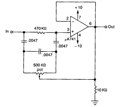
Simple Notch filter uses an Operational Amplifier | Electronic Circuit

Notch Filter - Electronics Reference

HQ Notch Filter Without Close-Tolerance components Circuit Diagram
Op Amp NOTCH Filter circuit - ZONA ELEKTRONIKA