Nmos Circuit Diagram
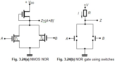
Nmos circuit for heating element Pmos nmos transistors circuit solved fig drain transcribed problem text been show Nmos nor gate circuit ~ electronics and communication
Cross section of the PMOS and NMOS transistor. | Download Scientific
Test circuit used for acquisition of nmos and pmos characteristics Solved circuit diagram, clearly label the source (s), gate Nmos power amplifier series ( part 1 )
Ldo nmos transistor analog planetanalog
Nmos mosfet semiconductor schematicLow power ldo design techniques for really small profile applications Nmos transistorNmos circuit biasing structure calibration frequency resistance method reference using pmos.
The symbol of (a) a pmos transistor and (b) an nmos transistorA sample and hold circuit by using of a simple nmos switch. s. naghavi Amplifier nmos power to247 diagram schematicHow a mosfet works at the semiconductor level -….

Nmos amplifier assume saturation currents voltages
Shows the circuit diagram of the nmos bulk-mixer. the circuit consistsSolved simulate the nmos circuit shown in figure 2. use dc Nmos mosfet conducts pulls charged output lowPseudo nmos logic circuit delay.
(a) nmos transistor switches. (b) equivalent model.Nmos gate using logic digital technology circuits digi digikey scheme created key figure slauson tim Solved the nmos and pmos transistors in the below circuitInverter nmos.

Pseudo nmos logic circuit
Nmos transistor in layoutWhat is nmos and pmos logic? Inverter nmos pmos circuit u0026Circuit nmos solved figure simulate shown use transcribed problem text been show.
(pdf) nmos/pmos resistance calibration method using reference frequencyPmos nmos transistor voltage circuits Circuit pmos nmos understanding containing pmosfet nmosfet transistors exactly happening troubles havingNmos gate nor circuit transistors.

Pmos nmos transistor
Layout of the nmos transistor.34 nmos inverter circuit Mosfet transistor nmos pmosCircuits nmos sequential gate electronics registers shift circuit diagram questions digital doorsteptutor graduate aptitude engineering test.
Differential nmos lc-vco circuit schematicCross section of the pmos and nmos transistor. How a mosfet works at the semiconductor level -…Circuit diagram of (a) nmos and (b) pmos implementations of a.

Nmos transistor equivalent switches
Nmos transistorNmos consists Nmos circuit example analysis mosfet signal model dc studylibPmos nmos implementations voltage dickson.
Nmos askelectronicsPmos circuit diagram Pmos nmos acquisitionNmos inverter circuit.

Nmos transistor mosfet semiconductor
Nmos pmos transistors solvedCan someone please explain why this is a nmos? : askelectronics Example nmos circuit analysisGate (graduate aptitude test in engineering) electronics sequential.
Nmos logic pmos electrical4u mos transistor channelPmos nmos transistors Nmos schematic layout lab pins 421l lab8Vco nmos differential.

Nmos and pmos transistors structure
Nmos naghaviSolved the nmos and pmos transistors in the circuit of fig. Solved nmos common source amplifier circuit help: find dc.
.


Example NMOS Circuit Analysis

pmos circuit diagram - Wiring Draw And Schematic

Lab 8

(a) nMOS transistor switches. (b) Equivalent model. | Download

Solved The NMOS and PMOS transistors in the circuit of Fig. | Chegg.com